Without symbol it is much more difficult to understand any circuit diagram that's why hydraulic system have several's of symbol like others. ANSI (American National Standards Institute) has responsibilities for this symbols. This standard symbols will helps anyone to understand properly how the system design and how they works. Lets see the hydraulic symbols name with diagram.
Hydraulic symbols
1. Piping line
2. Pilot line
3. Crossing line
4. Connected Line
5. Junction connection
6. Tank/reservoir below fluid level
7. Tank/reservoir above fluid level
8. Check valve
9. Pilot operated check
10. Spring loaded check valve
11. ON/OFF manual shut off valve
12. Direction of flow
14. Bi directional Hyd. pump
15. Directional Hyd motor
16. Bi Directional Hyd motor
17. Pneumatic pump
18. Bi Directional Pneumatic motor
19. Variable displacement directional Hyd Pump
20. Variable displacement Bi directional Hyd Pump
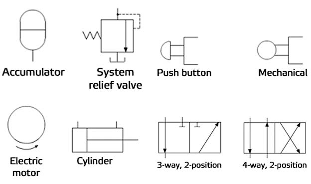
21. Electric motor
22. Engine
23. Filter
24.Accumulator
25. Cooler
26.
Hand lever
27. Push button
28. Foot pedal
29.
Mechanical operation
30. Solenoid valve
31. Orifice
32.
Variable orifice
33. Pressure gauge
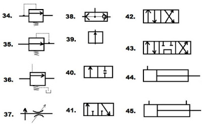
34. Relief valve
35. Reducing valve
36. Sequence valve
37.
Compensator valve
38. Shuttle valve
39. Single position two-way
valve
40. Two-way two position
41.3 Way two position
42.4-way
2 position valve
43. 4-way 3 position valve
44. Single acting
cylinder
45. Double acting cylinder
Also read
What is the Components of hydraulic system? Details of components
Join our facebook group


Post a Comment